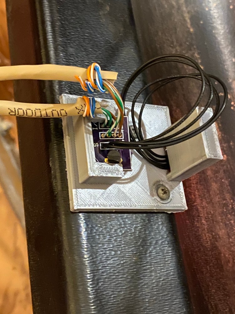
The custom PCBs for my sensor assembly arrived some time ago. Unfortunate I messed up and put the wrong foot print on the boards for my headers. After a long pause to figure out if redoing the board was best or just use what I already have I chose to use what I have. Instead of putting headers on I just soldered the wires directly to the board. While this made things more secure it also made things less flexible. When I started soldering I messed up one of my crimped connectors for the sensors. So I took the opportunity to just order some pre-crimped cables. The pre-made cables are far more secure than my home made cables. After a bunch of soldering and having to re-tin my iron tip I finished up the sensor breakouts.

The shape of the new PCBs was just off enough to require a slight change to the mounts. After some quick work in TinkerCad and hours printing the new mounts were ready. Once mounted and connected to the microcontroller scoring and ball counting is working perfectly.

Now that the machine is reliable it’s time to start work on the display. It will need to be converted to LED, rewired for low voltage, build new assemblies to hold the LEDs, and have a mess of new code written to pull it all together.

